Energy Meter
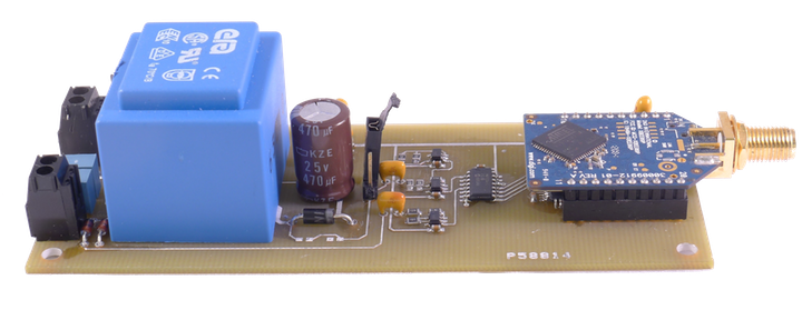
My buddy Frank (the guy talking way too fast above) and I designed an open source energy meter. It is still in early beta, but Frank’s about to be commissioned in the Navy, and I have a three month Merchant Marine cruise coming up, so neither of us will have time to work on it for a while. Anyways, it’s pretty awesome if I do say so myself. It’s similar to the Kill A Watt, but it’s wireless, uses mesh networking, and is scalable from a metering a single outlet to service as building’s primary energy meter.
Features
- Uses current transformer for shuntless current measurements
- Wireless (ZigBee)
- True RMS voltage and current measurements, for accurate readings with noisy loads
- Power factor calculated with Fast Fourier Transform, with possibility of using FFT for Total Harmonic Distortion calculation
- 8 core Propeller microcontroller running at 80 MHz allows for lots of number crunching
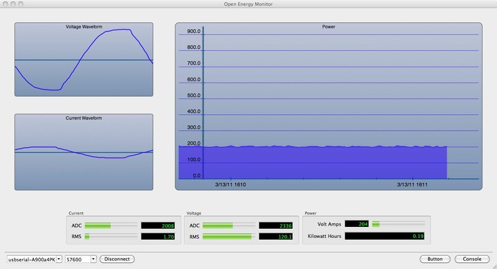
Also, I wrote an OS X Cocoa application for an interface to sensors. Currently, it only recognizes one sensor, but with a little modification I’ll make it handle any number of sensors. We even configured the sensors to occasionally send current and voltage waveforms. That’s mostly eye-candy, but could be useful to a utility to identify problems or particularly noisy loads.
TODO
- Design a board that fits a standard size box
- Add the ability to switch out current transformer’s burden resistance on the fly, depending on amperage, to allow for a wider range of current. Currently we’re getting accurate measurements from 10 mA to about 12 A, after that it starts clipping at the input of the op amp. For a house, there’s a much wider range of currents.
- Find wireless modules that allow for huge mesh networks. Big enough for all the houses in a small town to pass occasional readings to the utility.
If you’re interested in getting involved, let us know. You can check out the live code at our Google Code page.
Downloads
Design Summary from APPA Conference
 Thursday, March 24, 2011 at 17:09

Reader Comments (6)
Would this be possible to connect the system and see the mesh network using NetworkViewer from http://www.openecosys.org ?
Nice project, but I have one or two suggestions. First, get a steady cam even if you have to make it from parts at the hardware store. There's nothing more difficult to watch (for me anyway) than hand-held video that's completely unstabilized. My other suggestion would be to slow down on the description of the project.
No wonder the voltage on LVSENSE is distorted if you are also using the same winding to power a half-wave rectifier. Use a more capable transformer, a transformer with dual windings and a full-wave rectifier (better), or a totally separate transformer (best).
Also, the unconnected end of CT burden potentiometer should be connected - it will prevent an open-circuit CT voltage from appearing on op-amp's input in case potentiometer's wiper intermittently looses connection during rotation (what is common for low quality and/or old pots). You should also take this issue under consideration when designing burden resistor switching circuitry - it has to be continuous or make-before-brake solution.
Except for these issues it's quite a nice solution.
Shouldn't there be some isolation between main voltage and your electronics (opto-isolators, ...) ?
Yep. Still trying to figure out the best way to do it. Ill look if there are any reasonably priced linear optoisolators.
I've used these guys in the past : http://secomtel.com/UpFiles/Attach/2003/11/19/103521.pdf
I got them for about $2 a piece in quantity, though I'd like to find cheaper alternatives.