Transistor Shunt Voltage Regulator
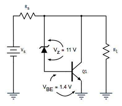
My buddies Frank, Joe, and I had some time to kill today so we decided to build a transistor shunt voltage regulator. We didn’t know correct terminology of the circuit topology at the time, and therefore couldn’t find any examples on the internet. But, we knew the basic topology of the circuit, and had plenty of transistors and zener diodes laying around, so we came up with the circuit shown in Figure 1. Again, we were shooting in the dark, so had to pick out components on gut feel and trial and error, but for a DC sweep to plot input/output characteristics we settled on Rs = 100 Ω, Rl = 470 Ω, a 13 V zener diode, and a 2N2219 NPN transistor.
 Figure 1—-Transistor Shunt Voltage Regulator
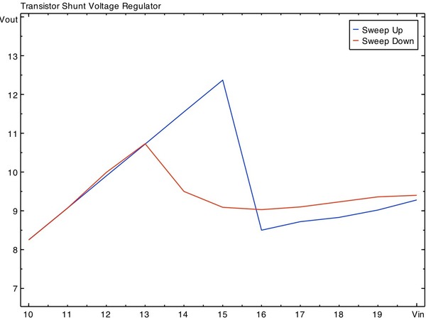
Now, something strange happened when we stepped Vin up from 10—20 V. From Vin = 10—15, Vout increased linearly, just as any voltage divider would. That is, since the zener hadn’t ‘turned on’, the transistor wasn’t sinking any current, and all the current was flowing through Rs and the load. But, when we increased Vin to 16 V, there was a sudden drop in Vout from 12.37 V to 8.50 V. We were puzzled, especially since it appeared as though the circuit was regulating after that, but at a much lower voltage than expected. The end result being plot of Vout/Vin with a strange dip it in (Figure 2). Even weirder, there appeared to be some hysteresis, or memory in the circuit, the plot of the DC sweep from 10—20 V does not match the plot of the sweep from 20—10 V.
 Figure 2—-Original circuit DC sweeps
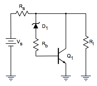
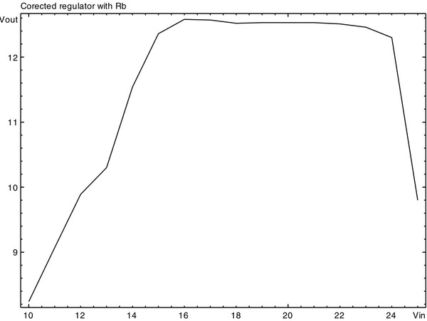
In comes our professor, Dr. Amani. He suggested adding some series resistance, in this case a 1k Ω chosen randomly (Figure 3). The result? A a very nice regulating curve (Figure 4), which was nearly identical in both 10—20 V and 20—10 V.
 Figure 3—-Rb added to original circuit
 Figure 4—-Correct circuit DC sweep
Why did the circuit need that resistor? And why did the original circuit have memory? I’m still trying to figure it out.
Download the Sysquake files used to create the plots.
 Share Article
Reader Comments (7)
I think it's pretty clear that the turn-on/turn-off I_B (+/-15 mA, IIRC) on the 2N2219 was to blame, but if you're not comfortable assuming that forgoing legitimate math to back it up we can run down the numbers tomorrow or Thursday. Instinctively it makes sense though, right? Also, maybe adding the 1k R_B kept I_B from ever reaching 15 mA, so it never "turned on," whatever that means in term of transistor operation.
I'm feeling the same thing as you, but I'd still like to do the math. Maybe Rs is too large?
Nevermind, I remember we tried putting in a smaller Rs and it got too hot.
i think you have to get it to 1.21 jiggawatts.
Jay,
Do you have access to the UN Navy NEETs Modules and/or the ET and FC rate traning manuals? They are a good gradient for basic electronics and circuit analysis. They are also in the public domain. Drop me a line if you are interested.
Charlie,
(Once upon a time a Destroyer Radarman - FC2)
You know, I really need to proof-read my posts before I send them. "UN Navy" WTF? N and S aren't even close on the keyboard! Brain not fully engaged...
I have them. I regret not getting the whole printed set before I left the Navy.