PCB Business Card
I’ve been seeing a lot of printed circuit board (PCB) business cards on the internet these days, particularly on hackaday, so I decided to jump on the nerd bandwagon and make my own. I searched google images for inspiration and found this one, which I thought looked pretty awesome. So I copied the general layout, but with a few minor changes. First, I designed my own circuit using a Propeller chip, 8 0603 (very small) LED’s, and a surface mount (SMT) battery holder. Second, instead of having white text on a black solder mask, I put the QR code and text on the solder mask layer. That way, the silver board will subtly show through from underneath.
I put the order in to Gold Phoenix last week. I choose their normal 155 in2 deal. It’s a really good price - without any option it’s $110. In my case, I ordered their thinnest PCB material, and added black solder mask. The total came out to $130 with shipping to the US. Expensive business cards at $6 each, but I don’t anticipate handing out too many and it would have cost way more if I had ordered them from an American company.
Here’s the board as sent to Gold Phoenix.;) Gerbv render of the Gerber files sent to Gold Phoenix
Gerbv render of the Gerber files sent to Gold Phoenix
As for the circuit, it really is overkill. I’m not actually going to be able to afford to populate the boards, but as long as I didn’t make any errors, it should work. The the propeller chip is $8, and all the other parts added to the price of the bare board will bring this card to almost $18.;) PCB business card schematic
PCB business card schematic
Download the Eagle Cad files.
 Jay Kickliter
Just came in the mail from Gold Phoenix. They came out better than I was expecting. I’m glad I went with exposed silver, instead of silkscreen, for the text and QR code. However, it’s a bit difficult to read under uneven lighting conditions.
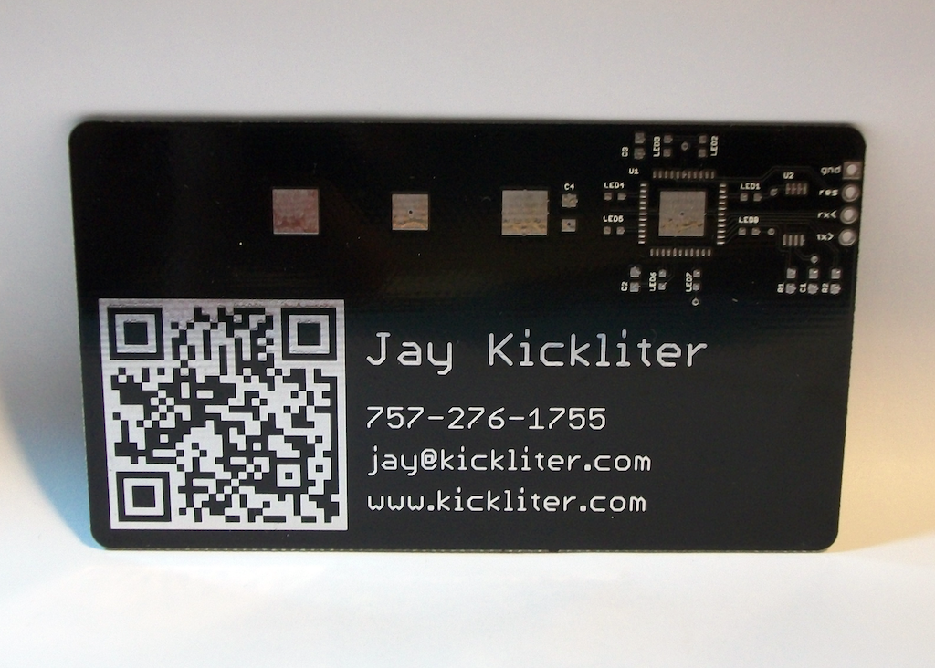
Jay Kickliter
I now take back what I said about not using silkscreen for the QR code. I still like the look of the silver text, but if anyone wants to do this I suggest you put your QR code on the silkscreen layer. I tested it with two different iPhone models, and both had a hard time reading the QR due to reflections.
Also, I failed to mention how great of job Gold Phoenix did on the board. I have no affiliation with them, by the way, I’m just impressed with their work. A few board have some missing silkscreen for the part names, and there are a few pin-sized holes in the back solder mask on a handful of board. But, the black solder mask is awesome looking; the photo I took doesn’t do it justice. Very glossy. Until I solder up some cards, I have no opinion of their etching abilities, but from what I’ve heard they do a good job with an acceptable percentage of boards with electrical errors.
I love to buy American, but these Chinese made boards are an order of magnitude cheaper than anything I could get made here. And from submitting my order to receiving the FedEx package was just a hair over two weeks.
electronics, microcontrollers | tagged ;)
;)
;)